|
|
|
Who's Online
There currently are 5973 guests online. |
|
Categories
|
|
Information
|
|
Featured Product
|
|
|
 |
|
|
There are currently no product reviews.
 ;
The AKAI 1720 model reel to reel tape recorder described in this Manual is quite an old unit - circa late 1960's. As a consequence, the description of the mechanical details - and adjustments thereof - is quite critical. The manual does this quite well. The schematics are also well presented and have detailed PCB overlays. Probably the only negative is that some half-tone detail has been lost from the original manual as it has been scanned in simple B&W.
 ;
Perfect source for service manuals: fast and professional transaction; high quality, perfect readable and largely scaleable PDF; complete schemes, diagrams and spare part list. Tnx a lot, cu again!!!!
;
I got your link from a friend and I must say that I am really satisfied with your service. Specially this B&O manual I didn't find anywhere on the web... but you could deliver it :-) . You deliver very fast and the copy is of good quality. So your webpage is bookmarked. Thanks
;
This was the Sony CCU-500A Service manual I was looking for.
The price was reasonable.
The permission to download was quck.
I will use Owner-Manual.com for all my manual needs.
;
Excellent printing quality.
A complete and very usefull service manual with all details.
GREAT SERVICE AT VERY LOW PRICE!
A+++++++++++++++++++++++++
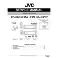
QL21,QL74:LC74781 Q601:YSS912
SDOB0 SDOB3
Microprocessor Coefficient /
SDOB Interface
/CSB
SDBCK1 Control Registers /SDBCK0 SDWCK1
SCK SI
24 * 16 Sub DSP
SDBCK0 SDWCK0
OVFB RAMA0 16 RAMOEN RAMWEN RAMCEN
SDIB Interface SDIBSEL
SDOB1 LS, RS
RAMD0 7
SDIB3 SDIB2 SDIB1 SDIB0 SDOA2 SDOA1 SDOA0
MUTE Operating clock Interface
C, LFE
SDOACKSEL SDIBCKSEL SDOBCKSEL
SDOB2 SDIA1
L, R
SDOA Interface
OPORT0 7 SCK SI SO /CS
24 * 24 Main DSP AC-3/Pro Logic/DTS
Interface Program RAM
SURENC STREAM 0 7
Decoder
NONPCM
CPO
Input Buffer
IPORT0 7
XO XI
Control signals
SDIA Interface SDIASEL
KARAOKE ExternalRAM
CRC
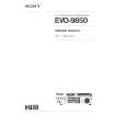
No. 1 2 3 4 5 6 7 8 9 10 11 12 13 14 15 16 17 18 19 20 21 22 23 24 25 26 27 28 29 30 31 32 33 34 35 36 37 38 39 40 41 42 43 44 45 46 47 48 49 50
NAME I/O FUNCTION VDD1 - +5V power supply (for I/Os) RAMCEN O External SRAM Interface /CE RAMA16 O External SRAM Interface address 16 RAMA15 O External SRAM Interface address 15 SDIB0 I+ PCM input 0 to Sub DSP SDIB1 I+ PCM input 1 to Sub DSP SDIB2 I+ PCM input 2 to Sub DSP XI I Crystal oscillator connection or input external clock (12.288 MHz) XO o Crystal oscillator connection VSS - Ground AVDD - +3.3V power supply (for PLL circuit) SDIB3 I+ PCM input 3 to Sub DSP TEST Test terminal (to be open in normal use) TEST Test terminal (to be open in normal use) OVFB O Detection of overflow at Sub DSP DTSDATA O DTS data detection (Refer to "Status Register".) AC3DATA O AC-3 data detection (Refer to "Status Register" .) SDOB3 O PCM output from Sub DSP CPO A Output terminal for PLL, to be connected to ground through the external analog filter circuit. (Refer to "External Circuit for PLL" .) AVSS - Ground (for PLL circuit) VDD2 - +3.3V power supply (for core logic) SDOA2 o PCM output from Main DSP (C, LFE) SDOA1 O PCM output from Main DSP (LS, RS) SDOA0 O PCM output from Main DSP (L, R) RAMA14 O External SRAM Interface address 14 RAMA13 O External SRAM Interface address 13 RAMA12 O External SRAM Interface address 12 RAMA11 O External SRAM Interface address 11 RAMA10 O External SRAM Interface address 10 VSS - Ground VDD1 - +5V power supply (for I/Os) OPORT0 O Output port for general purpose. (Refer to " OPORT Register") OPORT1 O Output port for general purpose. (Refer to " OPORT Register") OPORT2 O Output port for general purpose. (Refer to " OPORT Register") OPORT3 O Output port for general purpose. (Refer to " OPORT Register") OPORT4 O Output port for general purpose. (Refer to " OPORT Register") OPORT5 O Output port for general purpose. (Refer to " OPORT Register") OPORT6 O Output port for general purpose. (Refer to " OPORT Register") OPORT7 O Output port for general purpose. (Refer to " OPORT Register") VSS - Ground VDD2 - +3.3V power supply (for core logic) RAMA9 O External SRAM interface address 9 RAMA8 O External SRAM interface address 8 RAMA7 O External SRAM interface address 7 SDOB2 O PCM output from Sub DSP SDOB1 O PCM output from Sub DSP SDOB0 O PCM output from Sub DSP SDBCK1 I+ Bit clock input for SDOA, SDIB, SDOB. (Refer to " SDOA, SDIB, SDOB Register") SDWCK1 I+ Word clock input for SDOA, SDIB, SDOB. (Refer to " SDOA, SDIB, SDOB Register") VSS - Ground
CRC (30MHz) Data RAM AC3DATA ERAMUSE Delay RAM DTSDATA PLL
SDIA0
No. 51 52 53 54 55 56 57 58 59 60 61 62 63 64 65 66 67 68 69 70 71 72 73 74 75 76 77 78 79 80 81 82 83 84 85 86 87 88 89 90 91 92 93 94 95 96 97 98 99 100
NAME VDD2 NONPCM CRC MUTE KARAOKE SURENC /SDBCK0 RAMA6 RAMA5 VSS RAMA4 /lC TEST RAMA3 /CSB /CS SO SI SCK RAMA2 VDD1 RAMD0 RAMD1 RAMD2 RAMD3 RAMD4 RAMD5 RAMD6 RAMD7 VSS VDD2 SDWCK0 SDBCK0 SDIA0 SDIA1 RAMA1 RAMA0 RAMWEN RAMOEN VSS VDD2 IPORT7 IPORT6 IPORT5 IPORT4 IPORT3 IPORT2 IPORT1 IPORT0 VSS Note )
I/O O O O O O O O O O Is O Is+ Is Ot Is Is O I+/O I+/O I+/O I+/O I+/O I+/O I+/O I+/O I I I I O O O O I+ I+ I+ I+ I+ I+ I+ I+
FUNCTION +3.3V power supply (for core logic) Detection of non PCM data. (Refer to " Status Register") Detection of AC-3 CRC error. (Refer to " Status Register") Detection of auto-mute. (Refer to " Status Register") Detection of AC-3 karaoke data. (Refer to " Status Register") Detection of AC-3 2/0 mode Dolby surround encoded input (Refer to " Status Register") Inverted SDBCKO clock output (refer to " Block diagram") External SRAM Interface address 6 External SRAM Interface address 5 Ground External SRAM Interface address 4 Initial clear Test terminal (to be open in normal use) External SRAM Interface address 3 Sub DSP Chip select Microprocessor interface Chip select Microprocessor interface Serial data output Microprocessor interface/Sub DSP Serial data input Microprocessor interface/Sub DSP clock input External SRAM Interface address 2 +5V power supply (for I/Os) External SRAM Interface data (STREAM 0 output when External SRAM is not in use) External SRAM Interface data (STREAM 1 output when External SRAM is not in use) External SRAM Interface data (STREAM 2 output when External SRAM is not in use) External SRAM Interface data (STREAM 3 output when External SRAM is not in use) External SRAM Interface data (STREAM 4 output when External SRAM is not in use) External SRAM Interface data (STREAM 5 output when External SRAM is not in use) External SRAM Interface data (STREAM 6 output when External SRAM is not in use) External SRAM Interface data (STREAM 7 output when External SRAM is not in use) Ground +3.3V power supply (for core logic) Word clock input for SDIA, SDOA, SDIB, SDOB (Refer to " SDIA, SDOA, SDIB, SDOB Register") Bit clock input for SDIA SDOA SDIB SDOB (Refer to " SDIA, SDOA, SDIB, SDOB Register") AC-3/DTS bitstream (or PCM) data input for Main DSP (Refer to " SDIA Register") AC-3/DTS bitstream (or PCM) data input for Main DSP (Refer to " SDIA Register") External SRAM Interface address 1 External SRAM Interface address 0 External SRAM Interface /WE External SRAM Interface /OE Ground +3.3V power supply (for core logic) Input port for general purpose (Refer to " IPORT Register") Input port for general purpose (Refer to " IPORT Register") Input port for general purpose (Refer to " IPORT Register") Input port for general purpose (Refer to " IPORT Register") Input port for general purpose (Refer to " IPORT Register") Input port for general purpose (Refer to " IPORT Register") Input port for general purpose (Refer to " IPORT Register") Input port for general purpose (Refer to " IPORT Register") Ground Schmidt trigger input terminal Input terminal with a pull-up resistor Digital output terminal Tri-state digital output terminal Analog terminal
43
Is : I+ : O: Ot : A:
44
|
|
|
> |
|